[MLC] Kupplungen, Bremsen, Kleinkrams…
Hallo zusammen,
hier habe ich weiteren Baufortschritt für euch dokumentiert. Eine Knacknuss waren die beiden Einrück-Spindeln für die Kupplungen. Ich habe mich für den Nachbau des Systems nach Wern-Patent entschieden, wie es auch Orr&Sembower verwendet wird.
Zum Einrücken der Kupplung wird die Seiltrommel seitlich verschoben und hierzu ist eine bestimmte Gewindespindel notwenig. Ich habe nach langem Tüfteln einen Weg gefunden diese Spindeln selber herzustellen, denn man benötigt eine mit Links-, und eine mit Rechtsgewinde.


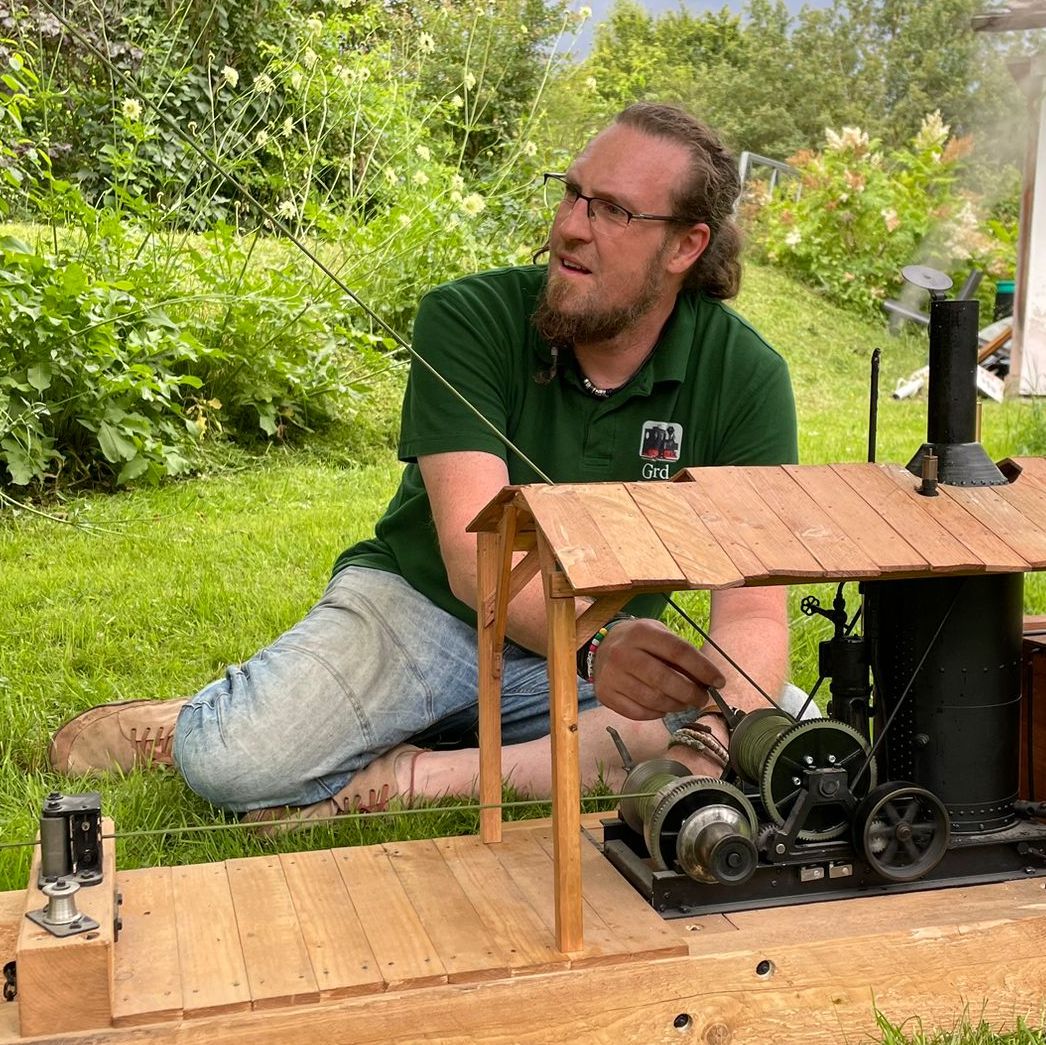
Auf der Fräse habe ich den Schraubstock im Winkel aufgespannt und konnte so in ein Stück 8×1,5mm Rohr einen schräge Nut einfräsen. Diese Rohlinge wurden dann auf einen 5mm Messingdorn aufgelötet und in die finale Form gebracht.
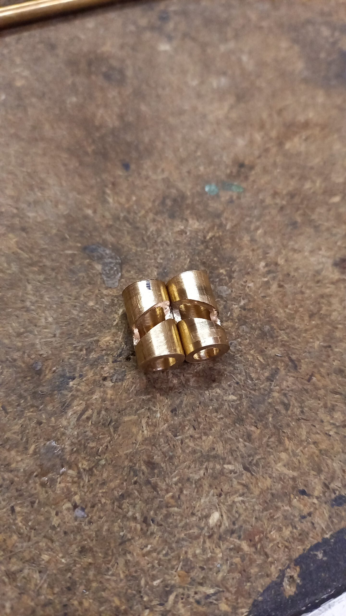
Für das Gegenstück wurden die Rohlinge aus je zwei Stahlstücken hart verlötet und dann auf der Fräse nach Skizze in Form gebracht. In der Bohrung bewegt sich die Messingspindel von oben. Durch das kleine Loch wird ein 3mm Passstift eingeschlagen, der dann in der Nut läuft und so die Spindel beim drehen vor und zurück bewegt.
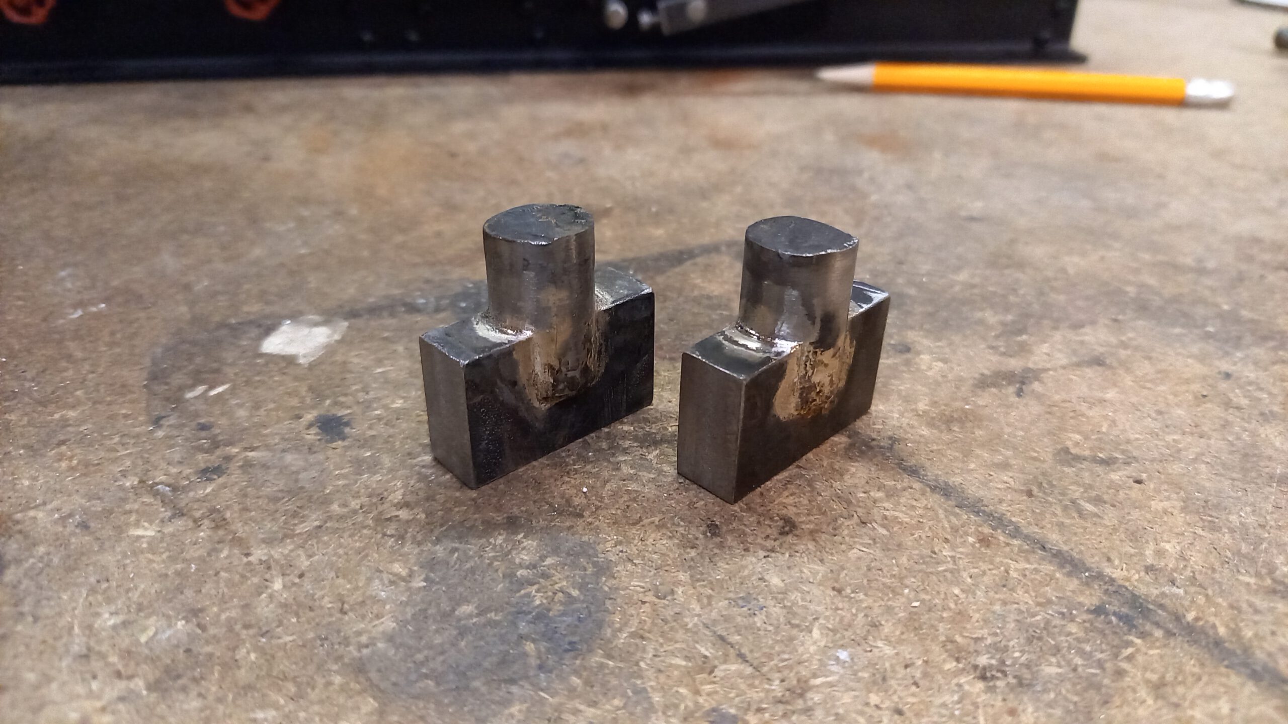

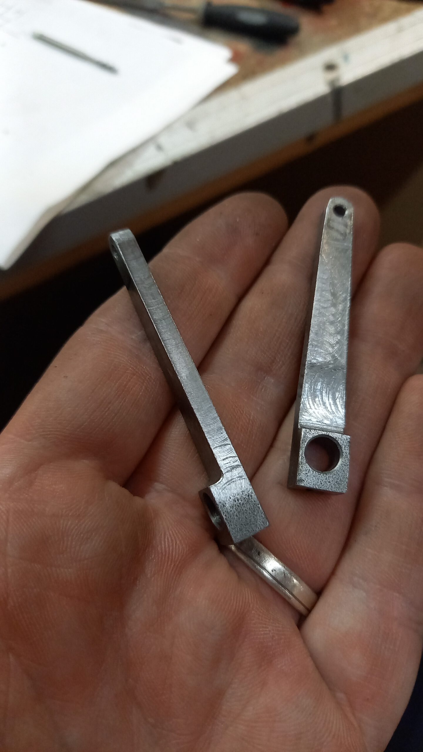
Die Messingspindel drückt dann über eine Druckstange in der hohlen Hauptwelle auf einen Mitnehmer, der schließlich die Seiltrommel gegen die Kupplungsscheibe drückt. Dazu brauchte es natürlich noch passende Hebel, ebenfalls aus Stahl gefräst.

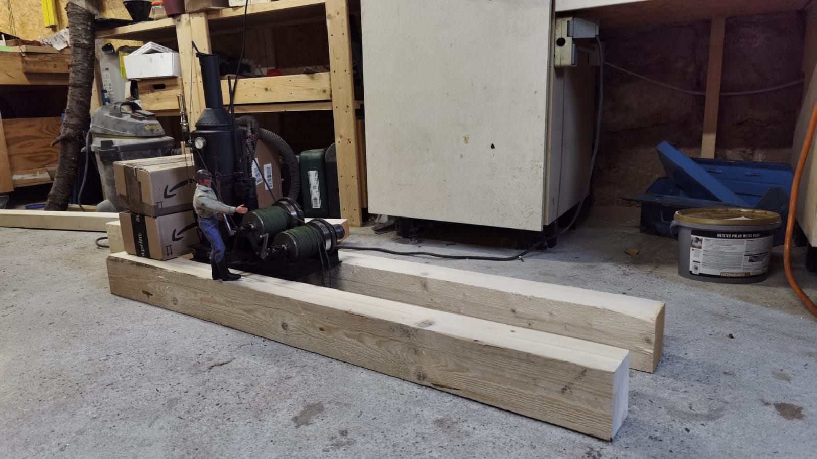
Letzte Kleinteile waren dann noch sie Bremspedale für die Bandbremsen. Letztere laufen auf der Kupplungsglocke. Damit ist die eigentliche Maschine der Donkey fast komplett. Das letzte Bild zeigt einen Ausblick auf den nächsten Beitrag. Dann wird der Schlitten gebaut und manch weiteres Zubehör.
Bis dahin beste Grüße,
Gerd